
Click here for MegaSquirt® MegaManual™ Information, Guides, and Links

The major new feature in MicroSquirt® v2.8+ embedded code is the capability to use two inputs and two outputs for ignition. This allows a number of possibilities in addition to the tach input (one tach input pulse per ignition output pulse) and the missing tooth code that was already there. The new options allow independent dual outputs for odd fires engines (such as the V-twins in many motorcycles), as well as camshaft synchronization for crank wheels and dual outputs.
Note that Dual Spark usage precludes the use of Ford's EDIS ignition system, and trigger return cranking mode cannot be used either.
The hardware is based on MegaSquirt-II™ hardware. The processor is the same. However, two processor pins were 're-purposed' to become the second spark input and output. The additional ignition input #2 (VR2in on Ampseal pin #4) is taken from the injector driver 1 pulse width modulation (PWM) processor pin (PT2), and the second ignition output (IGN2 on Ampseal pin #11) comes from the Injector 2 PWM pin (PT4). The result is that for MicroSquirt® you can not have injector PWM current limiting control (since these ports are now performing the second ignition function). It is recommended that you add the appropriate current limiting injector resistors if you are running low impedance injectors.
The 'original' MS-II™ ignition I/O are on PT0/PT5, and they are designated "Input 1" and "Output 1".
| Processor Port | Ext. Circuit | AKA. | Ampseal |
| PT0 TachIC | VRIN+/- OR OPTIN+/- | Input 1 | Ampseal 32/33 OR Ampseal 30/31 |
| PT2 TachIC2 | VR2IN+ | Input 2 | Ampseal 4 |
| PT4 IGN2 | IGNOUT2 | Output 2 | Ampseal 11 |
| PT5 IGN | IGNOUT | Output 1 | Ampseal 12 |
The Dual Spark option in v2.8+ code allows:
| MegaTune Option under 'Advanced Ign./Dual Spark' | Total Teeth | Missing Teeth | Crank Input | Cam Input | Output Pattern | Typical Usage (others possible) | |
| Single Spark (MS-II™ and MicroSquirt®) | |||||||
| Tach Input | No dual spark | Set M=0 | n/a | Input 1 | n/a | Output 1 only | distributor |
| Missing Tooth | No dual spark | M | N | Input 1 | n/a | Output 1 only | distributor with missing tooth crank wheel |
| MegaTune Option under 'Advanced Ign./Dual Spark' | Total Teeth | Missing Teeth | Crank Input | Cam Input | Output Pattern | Typical Usage (others possible) | |
| Dual Spark (MicroSquirt®; MS-II™ requires modifications - see below) | |||||||
| 1. Independent Dual Ignition | |||||||
| a. Dual Crank Sensors | Dual tach inputs | Set M=0 | n/a | Input 1 & Input 2 | n/a | V-Twin odd-fire, 2 crank triggers | |
| b. Dual Cam Sensors | Dual tach inputs | Set M=0 | n/a | n/a | Input 1 & Input 2 | V-Twin odd-fire, 2 cam triggers | |
| 2. Normal Crank Trigger w/ Cam Synch (cam sync can be set to rising or falling edge) | |||||||
| a. Tach trigger | M=cyl/2 | N=0 | Input 1 | Input 2 | Output 1/2 alternate | 2-cylinder COP with distributor trigger (or crank teeth = number of cyl/2) + cam trigger | |
| b. M-0 crank wheel | M (≠0) | N=0 | Input 1 | Input 2 | Output 1/2 alternate | 1 or 2-cylinder COP with flywheel trigger + 1 tooth cam trigger | |
| c. M-N crank wheel | M (≠0) | N (≠0) | Input 1 | Input 2 | Output 1/2 alternate | 1 or 2-cylinder COP with crank wheel + cam trigger | |
| 3. M-N Crank Wheel w/ No Cam Synch | |||||||
| a. M-N crank wheel | Single crank wheel input | M (≠0) | N (≠0) | Input 1 | n/a | Output 1/2 alternate | 1, 2 or 4-cylinder wasted spark, crank trigger and no cam trigger |
| b. M-N crank wheel | Two crank wheel inputs | M (≠0) | N=0 | Input 1 | Input 2 | Output 1/2 alternate | 1, 2 or 4-cylinder wasted spark, crank wheel and 1 tooth crank trigger |
| 4. M-N Cam Wheel Only (no crank wheel) | |||||||
| a. M-N cam wheel | Single cam wheel input | M (≠0) | N (≠0) | n/a | Input 1 | Output 1/2 alternate | 1 or 2-cylinder COP, cam synch but no crank signal |
| MegaTune Option under 'Advanced Ign./Dual Spark' | Total Teeth | Missing Teeth | Crank Input | Cam Input | Output Pattern | Typical Usage (others possible) | |
|
1.Independent dual ignition: This would typically be used for a two cylinder motor, but also can be used with a 4 cylinder engine and wasted spark. It uses two independent tach inputs on VRin1 and VRin2 (NOT a wheel input in the sense that there are not many teeth, just one per cylinder). It is intended primarily for 2 cylinder 'odd-fire' engines. Such engines include the Harley-Davidson (45°), MotoGuzzi (90°), Ducati (90°), Suzuki (75°), and Honda (52°) V-twins.
Alternating tach pulses from two crank or cam wheel sensors (which are physically offset with respect to each other) are fed to the two ignition input circuits and they produce two ignition outputs to separate coils. This can be odd or even fire - it doesn't matter because the pairs of input/outputs are independent. Input 1 triggers one injection channel (INJ1) and one ignition channel (Output 1), the other input (Input 2) triggers the other coil (Output 2) and injector bank (INJ2). Global things like RPM, etc. are computed from the channel 1 input. Since they are independent, the crank degree spacing between them (i.e. delta T between channel one and channel 2) does not matter. So the unit supports odd-fire, and it also injects based on which input (Input 1 fires injector 1, Input 2 fires injector 2). If you have an even fire engine, then try to make the input sensors 180° apart (i.e. directly opposite). With independent dual inputs and outputs, the odd-fire angle is generally built into the sensor location from the factory to reflect the offset in firing of the two cylinder banks. If this is the case, do NOT set the second output offset (odd angle) under Advanced Ignition menu. Otherwise the offset would be applied twice, which would not be correct. In this mode you cannot set the 'toothed wheel', 'trigger return', or 'EDIS' options - they won't work. Also, set the ignition ISR time mask, and the percent mask the same as in non-Dual Spark mode. | |
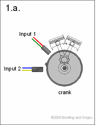 | a. Crank trigger: This is for dual independent crankshaft sensors. The number of teeth on the crank wheel must be the one-half (½) the number of cylinders. For a V-twin, this single tooth results in two tach signals per revolution, one from each sensor. This will run the coils in 'wasted spark' mode (for a 4 stoke engine), where they will fire on the compression and exhaust strokes.
This option is like having 2 independent 1 cylinder engines with coil or magneto driven ignition. They can be odd fire because you set the tach inputs physical sensor phasing to match the odd fire angle, but leave Odd angle as 0. This setup is wasted spark since the tach signal comes once per crank revolution - that is it is a crank mounted signal. If you have the signals coming from a cam so that each is once per 2 revs, then you choose option 1.b. Also, note that when calibrating the timing with a timing light, you should first use the trigger wizard to calibrate the timing of Output 1 to the value shown in the trigger wizard in MegaTune, then adjust the 'Offset (advance) of Output #2' until the timing reported in MegaTune for sparks from the coil(s) hooked to Output 2 matches what you measure with the timing light. Toothed wheels (M-N, or M-0 where M > tach pulses) are not allowed (and no EDIS, no trigger return cranking mode). So the number of teeth must be set to 0 (zero). |
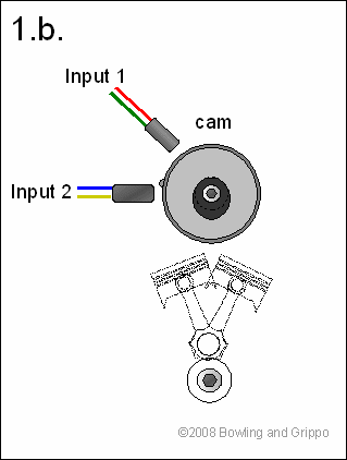 | b. Cam trigger: This is for dual independent camshaft sensors. The number of teeth on the cam wheel must be the same as ½ the number of cylinders. For example, for a 2 cylinder engine this is one tooth on a single cam wheel, or one tooth on each of two cam wheels in an overhead cam configuration.
Toothed wheels (M-N, or M-0 where M > tach pulses) are not allowed (and no EDIS, no trigger return cranking mode). So the number of teeth must be set to 0 (zero). Since there are only two outputs, 2-cylinder COP is the normal application for this, but driving 2 coils for 4-cylinder wasted spark is also possible in this mode. |
| 2. Normal trigger on input 1 with rising/falling edge cam synch on Input 2. The edge for the first trigger is selected in the usual way and there is an independent edge selection for the cam synch. With this setup there are 3 possibilities: | |
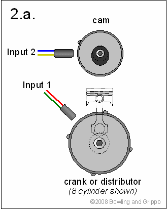 | a.Tach trigger on Input 1. A 'tach input' is an input that occurs once for every spark event that needs to happen. For a 4 stoke cycle engine, and 8 cylinders, this is 4x per revolution. For a 4-stroke, 4 cylinder, it is 2x per rev, etc. Typically, such a signal comes from a distributor, but it can also come from a crank wheel (2 teeth for a 4 stroke/4cyl, 4 teeth for a 4stroke/8cyl, etc.). Output 1 is fired on the first tach pulse after the cam pulse is sensed. The next tach pulse fires output 2, and they continue alternating thereafter. If the cam does not continue to come in between the last and first cylinder tach pulses, then a resynch occurs. |
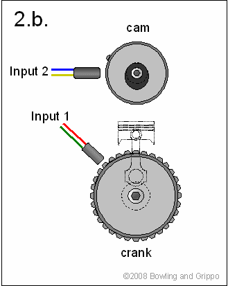 |
b. M - 0 toothed wheel (no missing teeth - for example a flywheel) on input 1 and a rising or falling edge 1 tooth cam synch is on input 2. This is handled the same as in (a), except the first tooth after cam synch starts the action and the appropriate number of 'skip teeth' thereafter are ignored (except for time error checking/ correction) until the next 'tach' tooth.
M, the total number of teeth, must be such that MegaSquirt-II will be able to 'skip' a certain number of teeth so the only the right number of teeth are counted as 'tach signals' per revolution. In general, this is:
Alternatively, the total number of teeth must be a multiple of one half the number of cylinders for a 4 stroke (a multiple of the number of cylinders for a two stroke). See the missing tooth page for more information. Note the cam synch must be physically located so that it occurs just before the reference crank wheel tooth (and after the previous tooth), otherwise timing will be one tooth off. |
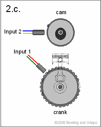 |
c. M-N toothed wheel on input 1. The cam synch on input 2 must be placed so that it occurs during the missing teeth. Ignition starts on the tooth after the missing tooth. If a cam synch has occurred just before this tooth, it fires on Output 1, otherwise it starts with Output 2. Thereafter the outputs alternate. This setup provides the fastest startup because you don't have to wait for cam synch. Note that the cam detection polarity (aka. "input edge capture") is independent of the crank detection polarity, and you must specify both.
For this option there can be no trigger return and no EDIS. Also, note that while having both a crank and cam signal gives us the information we need to control one coil per cylinder (COP), and sequential fuel injection, we only have 2 ignition outputs (and 2 injector outputs) so this is not possible with more than 2 cylinders on MicroSquirt® controllers.
M, the total number of teeth, must be such that MegaSquirt-II will be able to 'skip' a certain number of teeth so the only the right number of teeth are counted as 'tach signals' per revolution. In general, this is:
Alternatively, the total number of teeth must be a multiple of one half the number of cylinders for a 4 stroke (a multiple of the number of cylinders for a two stroke). See the missing tooth page for more information. |
 | 3. M-N toothed wheel comes in on Input 1 and there is no Input 2. The first tooth after the missing tooth starts the firing sequence on Output 1, then fires Output 2 after Skip teeth (= next tach), and alternates thereafter. This option provides 'wasted spark' coil firing for 1, 2 or 4 cylinders. For a 1 or 2 cylinder engine the two outputs must be tied to the single coil.
You can also do 2 or 4 cylinder wasted spark with this crank wheel only option. There are 2 flavors of this: Odd angle = 0 and != 0. The difference is that pure wasted only has one coil - and you have 2 outputs, so you have to tie them both together using a logic OR gate. Or you could ignore one output, but then MegaTune would display double or half the actual rpm. This setup has symmetric inputs and outputs - that is you fire each output every 180 deg and it is even fire. With odd-fire, you have to fire non-symmetrically, so you MUST have 2 separate coils which are fired separately every 180°, with the offset put into Odd Angle. |
 | 4. M-N Cam Wheel Only This option provides for a cam driven M-N wheel (1 input) which gives 2 cyl COP and is very like the M-N crank + cam synch setup (2.c.). |
To view the actual input signals from your vehicle, as seen by the processor, use the tooth analyzer package. You can download the code and corresponding Windows application here: www.microsquirt.info/tachref.htm
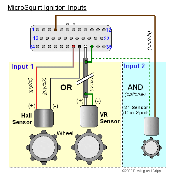
The code incorporates an 'odd-fire offset angle' for any of the dual spark modes. The offset advance is added to the 2nd output to advance(+) or retard(-) it relative to output 2 from an even fire engine. This should work for a 2 cylinder odd-fire engine with a missing tooth wheel mounted on the cam, and probably even for a crank mounted wheel in wasted spark mode.
Because there are two ignition outputs, there is more time for coil charging, but the code is more complex. The ignition triggering must be set up to follow a sequence of: tach in, wait to charge, charge, spark before next tach in. You can have ATDC timing by trigger offsetting everything, but then timing range is lost BTDC. This presents no problem on a 2 or 4 cylinder engine.
With the Dual Spark function enabled, the trigger offset should be set 'negative'. That is, there are always two choices for trigger offset. The timing looks as follows:
          ...----|<------ degrees between firings -------------->|----...
          ...----|--------------|--------------------------------|----...
          ...- tach1-----------TDC-----------------------------tach2 -...
          ...----|<--(+)x deg-->|<------(-)y deg---------------->|----...
For non-Dual Spark function, it doesn't matter which offset you choose because the dwell + spark sequence for a cylinder can be anywhere in the cycle, and we have generally used positive (+) degrees in the documents. But for Dual Spark, because it is too complicated and there is not enough RAM or CPU time, you must start and finish both dwell and spark within the time between 2 consecutive tach pulses. In this case we always want to use the negative y degrees, or else the math ends up coming out incorrect in the code.
For example, if tach1 occurs at a trigger offset of +40° BTDC, tach2 occurs -320° ATDC. For dual spark mode we always want a negative trigger offset, so you would use -320° instead of +40°.
The -320° offset seems unusual, but there is a reason for it. The original code started with a very robust triggering system where people could put their sensors anywhere and use any kind of advance with any kind of offset. This was a nightmare to code and impossible to maintain with the dual spark system, which was based on a strictly next cylinder firing setup. In fact it sets up to fire 2 cylinders before the actual spark occurs. This allows plenty of time for dwell at high rpm. To maintain the previous terminology for users as well as keeping the code consistent, the advance offset was left as it was, but whereas for the original (non-dual spark) system it was best to use a positive trig offset (but negative offsets would also work), while dual spark requires a 0° to negative (ATDC) advance offset.
If you try to put in -320° offset in some older MegaTune ini files, it won't allow it, so use the latest ini file which opens up the limits to +/359°.
Let's take the more specific case of a two cylinder sequential COP setup. This is illustrated in the figure below. Ignition output 1 (IGN1) is set up for dwell and sparking on the first tach pulse after cam synch is sensed. The output will then fire 'advance' degrees relative to the downstream cylinder 1 TDC (compression). The next tach pulse causes the processor to again set up for a dwell spark cycle 2 cylinders down, where cylinder 2 is at TDC. Note that if the cam signal does not continue to arrive between the same two teeth, then a resynch occurs.
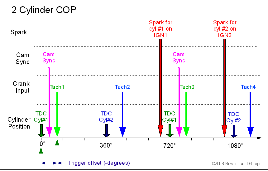
With only minor modifications this same setup can be used for a 4 cylinder, wasted spark, even fire engine. Just replace the cam synch with the first tooth after the missing tooth interval signifying the tach event. This assumes Delay_Teeth is 0. If it is one, it occurs one tooth later, etc. The same Delay_teeth variable can also be applied for cam synch/COP. The missing tooth also occurs every tach interval instead of only once every other, as does cam synch. For this wasted spark, even fire case, a 'wasted spark' coil is used to be used, so this compensates for the doubling of the cylinders to 4, and the rest of the timing and skip pulses will stay the same.
For 2 cylinder sequential fuel injection you must set 'alternating' injections. If you set 'simultaneous' you will defeat the whole purpose of sequential injection, as each cylinder will be injected twice instead of once per 720 crank degrees. The trim will work on the vehicle, but pulse width1 (pw1) in MegaTune will jump between trimmed and non-trimmed unless both are trimmed to the same value.
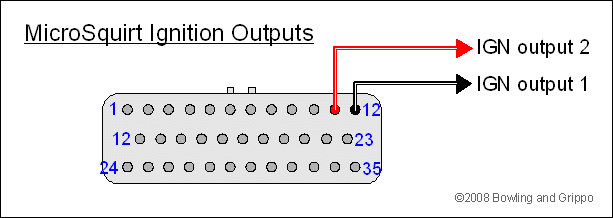
IMPORTANT! You can directly drive a maximum of one coil per ignition driver with MicroSquirt! This is because the coil driver (the VB921) can only sink enough current for one coil. That one coil can be a double ended 'wasted spark' type coil for two cylinders/coil (ex. the Ford EDIS4 coil pack with each coil driven by a separate driver), and it will be fine. But you CANNOT 'direct drive' two separate coils in wasted spark configuration driven directly off of one ignition driver (see below).
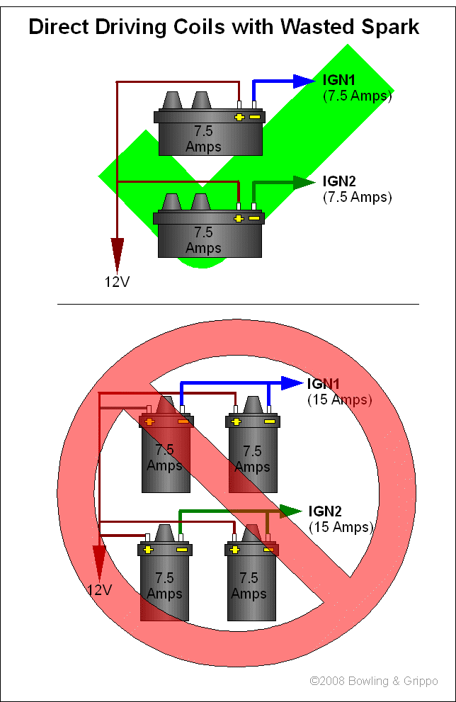
If you want to drive more than 2 coils, you might look at the 4-coil Bosch 211 igniter or the LSx series of coils with their built in igniters (and logic level signals on the ignition outputs).
The same pin routing as on the MicroSquirt® controller could be made on the MegaSquirt-II™ daughter board to enable dual inputs/outputs. You would do this by cutting the PWM traces into the logic chip and routing them to the appropriate output connector pins. The same software will then work in the same way on MegaSquirt-II™ and MicroSquirt®. It's not a difficult job for someone experienced in this, and would only take a few minutes to do. But it's not something you want to try without practice and the proper soldering iron and solder. If you don't make the mod to MS-II™, then do NOT set any of the Dual Spark options - they will not work. But you can use the v2.83+ code with the unmodified MS-II™ controller to get all the other features of this code.
To make the dual code spark mods on an MS-II™, the MM74HC00 NAND gate needs to stay in place on MegaSquirt-II™, but with some mods.
You can jumper the 2nd tach output and 2nd ignition output to come out externally through the DB37 if you like, using the SPR3 and SPR4 jumpers to DB37 pins 5 and 6. Output 1 will still be DB37 pin #36, Input 1 will be DB37 pin number 24 (i.e. the standard tach input and ignition output circuits/pins).
The ignition output will be a logic level driver. If you wish to control a coil with it, you will need to duplicate MicroSquirt®'s IGN2 VB921 output circuit shown here: www.microsquirt.info/us_hardware.htm from Pad #4.
For the second ignition input, you can duplicate either of the optoisolator or VR input circuits, with the resulting signal fed to Pad #1.
Note: The bootloader code (the code burned inside a virgin HCS12 to allow you to download new code) used for all MS-IIs to date turned off the injectors by turning off the PWM line going into the NAND gate along with the injector signal. Either one of these or both being 0 will turn off the injector. That's why everything has been working correctly. In MicroSquirt® there are no PWM lines so there is no NAND gate, nor is there a FET driver, and the B/L code was modified to turn off the injector signals at load time.
However, when the hack is made to the NAND gate for the Dual option mode, the PWM lines are disconnected, and the injector lines are high. So when the original PWM pin and injector pin are tied together, you get 2 highs going into the NAND gate. This doesn't happen in non-bootloader mode because the normal software turns the injectors off as required.
This means that if you make the Dual Spark modification on an MS-II™, you must unplug your injectors (or the injector fuses) or fuel pump during a bootload.
There is another solution to the injector lockup on bootloader problem. It is only viable if you're only using one of the ignition inputs, like a single 36-1 wheel; if you are using two different tach inputs for sync you cannot do the following.
The second fix is to rewire PWM1 output to the input of both NAND gates. So rather than unhooking PWM1 and PWM2, you unhook PWM2 (to use its output) and hook PWM1 where it was before. Instead of the modifications listed above, do the following:
Obviously you still can't use PWM. However with these modifications, when the bootstrap code pulls PWM1 low on boot, it will pull pins 1 and 4 on the NAND low, disabling both of the injector outputs. This means users do not need to pull fuses every time they use the bootloader to load new code.
MicroSquirt® One and Two Cylinder Dual Spark Ignition Options
(for MicroSquirt® code version 3.770 or higher)
One and two-cylinder engines, while seemingly simpler than those with more cylinders, pose some problems because of the way MicroSquirt® controller Dual Spark software handles the 2 ignition and 2 injector outputs that are capable of driving up to 2 banks of 4 cylinders each. It is the purpose of this document to describe how to configure various 1 and 2 cylinder engines to obtain optimal performance from the MicroSquirt® controller.
There are a number of configurations for controlling engines. In this section of this document we are considering only 1 and 2 cylinder engines which have one or more toothed trigger wheels to provide engine position information which can be used to control fuel and spark. These engines should be configured in your MicroSquirt® controller using the Dual/Multi Spark Option, with v3.730 or higher code version, which uses the Auto Trigger mode (click the link for more info). After configuring your wheel in accordance with the procedure given by this link, you will be ready to select the proper Dual Spark option. Dual Spark mode provides the following options:
The following table tells you how to configure the spark and fuel outputs for 1 or 2 cylinder engines when using the dual spark and dual injection outputs of a MicroSquirt® controller. For this table it was assumed that in Tuner Studio, under the Fuel Setup/ Injector Control menu, the number of squirts per engine cycle was set equal to the number of cylinders, The options for spark are to: use IGN1, 2 as separate outputs to drive 2 coils; leave IGN1, 2 as separate outputs but ignore IGN2; or to tie IGN1, 2 together using the procedure that follows after the Configuration table. The options which can be selected for each engine configuration are shown in the below table and considerations for choosing the best one for you are given in the Appendix (click link to go to Appendix). For fuel, it is possible to select Alternating or Simultaneous squirts in the TunerStudio Injection Control menu. When one or the other will give an advantage, this one is recommended in the table, and reasons can be found in the Appendix (click link to go to Appendix).
| Engine Configuration | Dual Spark Mode | Firing Order | IGN1,2 | Fuel Injection |
| Two Cylinder, 4-stroke | ||||
| Sequential, 2 Coils | Falling/Rising Cam Sync | Even or Odd-Fire | Separate | Alternating |
| Wasted, 2 Coils | Single Crank or M-0 w/ Crank Sync | Odd-Fire | Separate | Alternating |
| Wasted, 1 Dual Spark Coil | Single Crank or M-0 w/ Crank Sync | Even-Fire | Tie together | Alternating or Simultaneous |
| Separate, Ignore IGN2 | Alternating | |||
| One Cylinder, 4-stroke | ||||
| Sequential, 1 Coil | Falling/Rising Cam Sync | Even-Fire | Tie together | Simultaneous |
| Wasted, 1 Coil | Single Crank or M-0 w/ Crank Sync | Even-Fire | Tie together | Alternating or Simultaneous |
| Separate, Ignore IGN2 | Alternating | |||
| Cam Wheel or 2-Stroke (always sequential) |
||||
| 2 Cylinders, 2 Coils | Single Cam Wheel | Even or Odd-Fire | Separate | Alternating |
| 1 Cylinder, 1 Coil | Single Cam Wheel | Even-Fire | Tie together | Alternating or Simultaneous |
| Separate, Ignore IGN2 | Alternating | |||
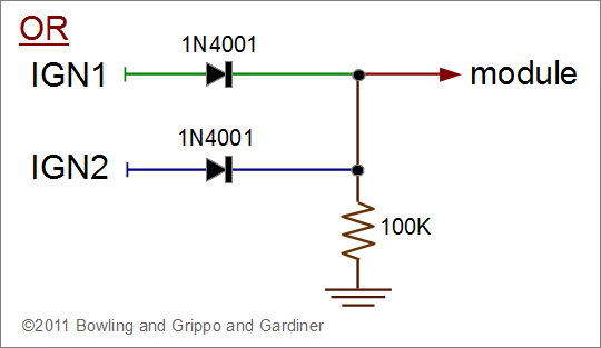
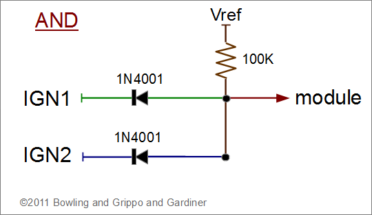
The ignition outputs from your MicroSquirt® controller are intended to go to an external ignitor that contains drivers capable of handling the current required to drive ignition coils. Many of these drivers, such as the BIP373s are in a wired-or configuration and their outputs can be tied directly together. NEVER join the 2 processor outputs directly. If your drivers can’t be tied together or you are using logic level ignitors, you can insert 1 diode (for example 1N4001 easily obtainable at Radio Shack) in series on the IGN1 output from the Ampseal and another on the IGN2 output, then tie the two diodes together to form a single output. A 100KOhm, 1/8 W, 25V pullup resistor, again easily available at Radio Shack, is also needed. These components are soldered into the circuit as shown in the below diagrams. Note the direction of the diodes, indicated by the band which is at one end of each diode, and whether the resistor is wired as pull up or pull down, are different depending on what kind of coil driver is being used.
In all cases where outputs are tied together, you must join only the outputs from the FET drivers, which are in a wired-or configuration. NEVER join the 2 processor outputs directly together. If this is ever necessary, they must go into a logic AND or OR chip/circuit. The circuit will prevent the ignition outputs from short-circuiting the processor outputs when one is trying to pull the signal high, and the other is trying to pull the signal low.
Here is an example of a logic OR circuit (high if either IGN1 or IGN2 are high, low otherwise; use if the dwell period of the signal needs to be high (to Vref = 5 Volts)):
Here is an example of a logic AND circuit (high only if both IGN1 or IGN2 are high, low otherwise; use if the dwell period of the signal needs to be low):
In addition to the above hardware modification, it is also necessary to tell the ECU that you have tied IGN1, 2 together. The program option for this is found in 3.x code versions and is only used for 1 and 2 cylinder engines. It can be found under the 'Ignition→Dual Spark' menu in TunerStudioMS. TuinerStudioMS limits it more specifically to the following configurations:
In the code itself, the above conditions are applied for 4-stroke engines, but for a 2-stroke, only the 1 cylinder conditions are applied. This just means that the 'tie ignition outputs' option has no effect on 2-stroke engines, which are always sequential, unless they are 1 cylinder. The latter has only 1 coil regardless of configuration, so it can make sense to tie the outputs together whether wasted or sequential.
Note also, if rpm is half or double what it should be, something is wrong with your input configuration. Go over the documentation, make timing diagrams, use a scope or stimulator and try to understand why the original configuration did not give you what you wanted. Don't just change inputs until the rpm comes out right – this may not give you the optimum setup.
For more information on dual spark concepts and the meaning and setting of the associated user parameters, see: www.megamanual.com/seq/multichannel.htm.