Click here for MegaSquirt® MegaManual™ Information, Guides, and Links
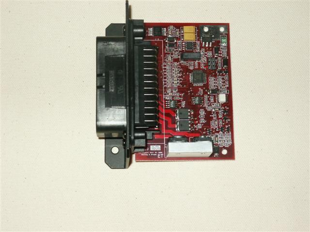
MicroSquirt® controller is a SMT version of the MegaSquirt-II and V3 main board versions of the MegaSquirt fuel injection controller. It is essentially the same board, with the exception that the fuel injector drives will max out at 5 amps each, enough to drive one low-impedance injector (or 4 high-impedance) per bank. The board uses the 35-pin AMPSEAL weatherproof connector. The physical size of a credit card - about 2.4" x 3.5" (61mm x 89mm) - connector included. It also has the single channel ignition driver and the VR and opto tach inputs.
MicroSquirt® controller is basically the same as MegaSquirt-II, with the main differences being the:
| Signal Volts | 1-Bar Sensor | 2-Bar Sensor | 3-Bar Sensor |
| 0 | 10 | 8.8 | 3.6 |
| 5 | 105 | 208 | 315 |
The pins are marked A-B-C on the sensor itself.
You don't have to use a GM MAP sensor, but you must know the pressure-voltage output curve of any other sensor you choose to use, as well as the pin-out.
MicroSquirt® Schematics
Here are the complete schematics:
Processor:
If your MicroSquirt has processor resets once installed, hooking up an external capacitor to Vref helps. Anything from 47µFarads up to 1000µF on the Vref to sensor ground return will help.
Sensors:
Ignition Input:
If you are triggering directly off the coil (instead of something like a missing tooth wheel or another relatively low-voltage signal), connect OPTOIN+ (Ampseal pin #30) to the coil's negative terminal as usual, but connect the OPTOIN- (Ampseal pin #31) to a 12V source rather than grounding it. This then uses the flyback spike off the coil as a trigger (rather than the 12 signal). Doing this reduces the energy dissipated in the circuit, prevent a thermal 'melt-down' of the components inside MicroSquirt®.
Tach Output:
Power Supply:

The regulator on the MicroSquirt® controller is a surface-mount version, and the heat sink is a copper area on the board plus the ground place (there are several "vias" stitched around the regulator for this).
The MicroSquirt® EFI controller, "unloaded", meaning just the input sensors (with MPX4250 MAP) and serial, no outputs, has an overall current draw of roughly 55 milliamps. The temperature rise of the regulator case is about 8 degrees above ambient temperature (°F) with a 13V input power supply.
The power dissipation of the regulator is simply the voltage drop across the regulator multiplied by the current. In the case above, the voltage drop is 13 volts minus 5 volts (Vout - Vin) = 8 volts. The power in watts is 8 * 0.055 = 0.44 watts. This is the amount of heat generated, and in this case the PCB has to dissipate about 1/2 of Watt of heat, which is it quite capable of doing.
Now, lets take an extreme case - say the same 13V power supply, but now try to draw 1 amp of current. The math is easy = 8 volts * 1 amp = 8 watts. Think about the MicroSquirt® PCB having to dissipate 8 watts! The board dimensions are 2.5 x 3.5 inches - not a lot of surface area to radiate heat, for sure.
The 20 milliamp number for the Vref spec came from temperature measurements of the PCB while adding load to the Vref line. The 20 milliamp additional load resulted in a PCB temp rise of 20 degrees above ambient. We could pull more current but then the board will rise in temperature. Think of a relly hot day where the ambient temp is high, then add another 20 degrees on top of this for the regulator.
On the PCB itself, there are two mounting holes right next to the regulator. They are there for those people who want to pull a little more current from Vref - simply add a heatsink setup to these mounting holes. How much more current you can obtain with this just depends - use an infrared thermometer and monitor the temp rise under the added load with the heatsink. The heatsink could also be bolted to the case as well.
People have asked why not split the Vref signal from the other 5V logic supply with another regulator on the MicroSquirt® board? Sounds good, however the same amount of heat is being dumped in on the PCB even with two regulators (we learned this lesson the hard way with the sequencer - hence the move to a switchmode setup there). Yes, both will contribute less, however the the board will again equalize at the same higher temperature. For those who have run the uS with the PCB out of the case you will notice the board get warm, and for the most part the heat travels across the entire board. This is because of the thermal sinking to the ground plane, which covers the majority of the board. If we had a really large PCB splitting the power up may work, but there really is not a lot of surface area to be dumping a lot of watts into, even if they (heat sources) are distributed.
Finally, remember this current rating is for the Vref +5V line. It does not affect the current capability of the drivers - these are referenced to the +12V battery and only share the common return ground path with the Vref. The relay drivers also are control +12V lines, only the gate drive for these drivers are using the +5V from the board, and this is already accounted for in the ~55ma number.
CAN Circuit:
Serial Circuit:
AMPseal Connector:
Ignition and Injector Drivers:
Fast Idle and Fuel Pump Circuits:
The schematics are available as PDF files as well: