Click here for MegaSquirt® MegaManual™ Information, Guides, and Links
The purpose of the easyVR circuit on MicroSquirt® was to avoid the need for turning pots as on the V3 board. Since the easyVR turns out to be not so easy, and since about 90% of people using the V3 board run fine with the pots fully CCW, Bruce has designed a daughter board with two VR circuits similar to the V3 board VR circuit. This will mount on the MicroSquirt® - there are mounting holes already on it - and will require soldering and routing a few wires down to the main board, but it should solve the problem.
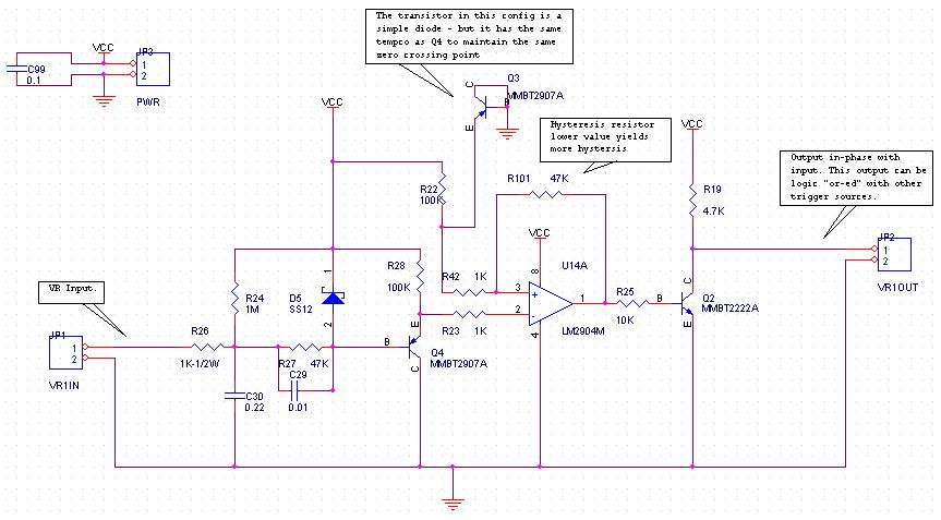
First thing to note is that the VR waveform is in-phase with the output square wave (the V3 circuit it is opposite). This is because of the extra transistor on the output on this new circuit, there because to allows a logical "or" with the opto circuit's transistor.
The triggering voltage points are around -20 milliVolts for the positive-to-negative direction, and about +70 milliVolts for the negative-to-positive direction - almost 100 milliVolts hysteresis.
So, the zero crossing point is a tad closer on the positive-to-negative transition, but in reality the VR waveform voltage, with engine running, is anywhere from a few volts up to 100 volts. A few volts, compared to the difference between -20mv or +70mv trigger point occurring at the steepest derivative point on the VR wave, results in it not making that much difference.
The hysteresis is about -150mv on the negative-going side, and darn near zero on the positive increasing side - and the polarity of the input and output are in-phase. This should be plenty for pretty much any starting situation (the easyVR circuit was about 0.7 volts), and the hysteresis resistors (R100 and R101) can be increased to make the circuit more sensitive, or even removed totally for no hysteresis at all.
Users should be able to verify this with your setup, get the engine to run and you should not experience any measurable timing shifts due to sensor polarity.
There are 6 wires to hook up to the existing MicroSquirt® board, and two standoffs. The board will mount in the case in one of the higher slots. First, remove the MicroSquirt® main board from the case:
In the upper right corner of the MicroSquirt® main board (ampseal connector to the left):
In the lower right corner of MicroSquirt® EFI controller, remove 4 components:
In the lower right corner of MicroSquirt® EFI controller, jumper the add-in board to the locations where you removed the components:
The VR board mounts in the case in one of the higher slots. A couple of "pine-tree" clips are supplied, these are push-pins that hold the new board above the MicroSquirt® board so that it slides in the case groove above it.
Finally, replace the MicroSquirt® main board into the case: