Click here for MegaSquirt® MegaManual™ Information, Guides, and Links
Introduction to the MicroSquirt® EFI controller
This archive document primarily applies to older V2 and V1 MicroSquirt® controllers.
For the latest V3 MicroSquirt® controller documentation, click this link: V3 MicroSquirt® Quickstart Guide
Search the MicroSquirt® manual:
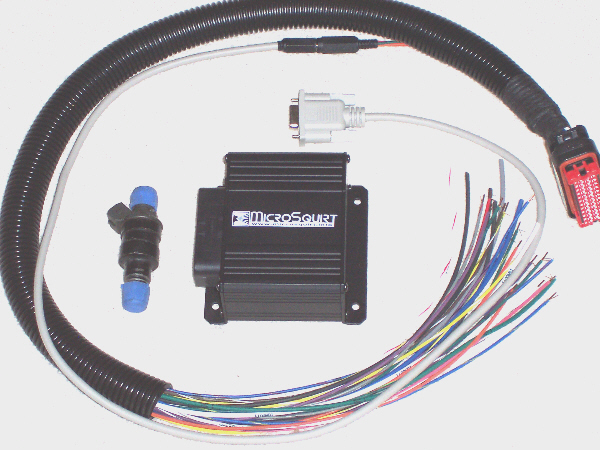
The MicroSquirt® EFI controller is a fully-assembled surface mount technology (SMT) version of the MegaSquirt fuel injection controller and is most like the MegaSquirt-II and V3 main board assemblies.
MicroSquirt® EFI controllers can use the same embedded code as MegaSquirt-II, and you can use any of the V2 code versions intended for the C64 version of the processor. However, MicroSquirt® has a few of it's own specialized hardware functions (dual spark is the main function) and these are only implemented in code version 2.8 and higher.
A MicroSquirt® EFI controller is essentially the same as the MegaSquirt-II/ V3 main board. It can use the same internal embedded code, tuning software, and ignition systems.
The main differences between MicroSquirt® EFI controllers and MegaSquirt-II™ controllers are the ignition input and output polarities, the injector drivers, MAP sensor, the FIdle capabilities, VR circuit, and connectors:
- Dual Spark capability: The major new feature in MicroSquirt® v2.822 embedded code is the capability to use two inputs and two outputs for ignition. See this document for more information.
- Input polarities are reversed for the VR input circuit - but not the opto input circuit, compared to the V3 main board because there is an extra transistor in the hardware. This means that where the MS-II documentation says to use 'rising edge' for MS-II, you use 'falling edge' with MicroSquirt, and vice versa. This is usually noted in the documents themselves. The ignition 'spark output' polarity ('going high' or 'going low' is the same as for the V3 Main board with MS-II).
For example, for direct coil control using the VR input circuit with a MicroSquirt® EFI controller, you set the parameters in MegaTune to:
- Coil Charging Scheme to 'standard coil charge',
- Spark Output to 'going high (inverted)'.
- No pulse width modulation (PWM) to limit injector current. The fuel injector drives will max out at 5 amps each, enough to drive one low-impedance (or 4 high-impedance) injector per bank. To get everything to fit without lots of heat sinking, MicroSquirt® uses the ST VND5N07 from STMicroelectronics to drive the injectors. This is not a 'peak and hold' driver, but it does clamp the current at 5 amps, so it can be used with one low-impedance injector per bank, however the close time may be a tad higher (or you can use resistors). For up to 4 high-impedance injectors per bank, it should work fine. For example, for motorcycle use MicroSquirt® will be perfect!
- No internal MAP sensor. In order to shrink the 'footprint' of MicroSquirt, the MAP sensor was left off the board. An external MAP sensor, such as those from General Motors products, can be used instead. See the MicroSquirt® hardware page for more information on MAP sensors.
- No stepper IAC control: In order to make room for the dual ignition inputs and dual outputs, the ability to to control a stepper IAC was removed. PWM Idle valves, as well as on/off idle valves, can still be used.
- Different connector and case. The MicroSquirt® board uses the sealed 35-pin AMPSEAL connector. Amazingly, the board is the physical size of a business card - connector and all. A MicroSquirt® EFI controller's board size, including the 35-pin AMPSEAL connector, is very small - 2.4" x 3.5" (61mm x 89mm), just slightly bigger than a credit card.
- Pre-loaded code: Unlike MegaSquirt-II™, the MicroSquirt®® EFI controller comes with the embedded code already loaded onto its processor. You can still upgrade to newer versions of the code as they are released, of course, but you won't have to load the code initially to get MicroSquirt® working.
- Access Board: For MicroSquirt® EFI controllers, we have made a simple "access" board, similar to the relay board for MegaSquirt (but that also includes some of the diagnostic LEDs of the simulator). They will be conformal coated, and these will be an assembled unit like the MicroSquirt. It is in the same form factor as the relay board (3 x 5 inch) and slides into the same case.
In most cases, you will use the MegaSquirt-II/V3 main board documentation for MicroSquirt. Exceptions are noted in the MicroSquirt-specific documentation for the:
The bootloader is externally accessible, so there's no need to open the case, even to load new code. And the serial RS-232 signals come out of the AMPSEAL connector (instead of a DB-9 on the front, as with MegaSquirt® controllers).1.
1 Temperature range: -40 to +105 deg Celsius
IP rating (estimated): IP54
Supply voltage operating range: +6.5V to +20V
Maximum voltage: +40V
Supply current: 45 milliamps
Injector driver max current: 5 amps (linear mode protection)
Ignition driver max current: 7.5 amps (linear mode protection)
Maximum permissible source from Vref: 20 milliamps
MegaSquirt® and MicroSquirt® controllers are experimental devices intended for educational purposes.
MegaSquirt® and MicroSquirt® controllers are not for sale or use on pollution controlled vehicles. Check the laws that apply in your locality to determine if using a MegaSquirt® or MicroSquirt® controller is legal for your application.
©2005, 2011 Bruce Bowling and Al Grippo and Lance Gardiner. All rights reserved. MegaSquirt® and MicroSquirt® are registered trademarks. This document is solely for the support of MegaSquirt® boards from Bowling and Grippo.